The Operation of marine propulsion systems using gas or other fuel with a low flash point as fuel
Design features of ships using gas or other fuel with a low flash point as fuel By their size and dimensions, gas tankers are divided into exactly the same types as oil tankers vessels:
✓short range, from 10,000 to 60,000 tons deadweight;
✓Panamax, from 60,000 to 78,000 tons deadweight;
✓Aframax, from 80,000 to 120,000 tons deadweight;
✓Suezmax, 120,000 to 200,000 tons deadweight;
✓VLCC (Very Large Crude Carrier), from 200,000 to 320,000 deadweight;
✓ULCC (Ultra Large Crude Carrier), from 320,000 to 550,000 deadweight. For correctness, it is worth noting that the last two types VLCC and ULCC if they are gas tankers are called VLGC (Very Large Gas Carrier) and ULGC (Ultra Large Gas Carrier), with the corresponding deadweight capacity of oil tankers, 200,000 -320,000 and 320,000 -550,000, respectively.
According to the types of cargo (gas) transported, gas carriers can be divided into two types :
✓LPG or LPG (liquefied petroleum gas)
✓LNG or LNG (liquefied natural gas) Petroleum hydrocarbon products such as propane and butane and their mixtures have been categorized by the petroleum industry as LPG.
Based on tanker design, LNG carriers are divided into two groups according to type of load-bearing systems:
✓integrated, or built-in cargo retention systems;
✓independent cargo retention systems. Integrated systems, or simply tanks/thermoses/tanks, form the main structural part of the ship, which is combined with the hull structure. They are primarily used in applications where liquefied petroleum gas (LPG) must be transported under near-atmospheric conditions, such as butane. Independent cargo containment systems are much more complex.
These tanks are self-supporting in nature and are not integral to the hull structure. Therefore, they do not place any stress on the ship’s hull. Independent systems are classified into three types. Type “A” tanks: These tanks are designed using the traditional method of ship construction. Liquefied petroleum gas as liquefied natural gas, under near-atmospheric conditions, can be transported in these tanks.
The design pressure of Type A tanks is less than 700 mbar.
The general design of a liquefied natural gas carrier vessel is almost the same as that of an oil tanker, with cargo tanks located along the entire length of the vessel’s hull. Ballast water cannot be carried in cargo tanks, so space for ballast is provided by using spaces in the double hull and hold.
The most notable and distinctive feature of Type A tanks is that a number of sources state that Type A tanks must have a secondary barrier to contain any leakage for at least 15 days. However, the system is classified as independent due to the way the tanks are installed in the housing. Because the aluminum tank structure is not integrated into the internal hull of the gas carrier and does not have any metal contact with the ship’s hull.
The interior shell lining and aluminum tank lining are separated by layers of wood, fiberglass, and balsa panels to insulate from outside temperatures. The balsa panels are held together with plywood on both sides, which are sealed using foam spacers. An inert space of 2 or 3 mm separates the inner fiberglass layer from the aluminum tank body. This space is provided for insulation and also allows for expansion of the tank structure. This type of installation makes this tank structurally independent in nature. Type “B” Tanks.
The design concept of such tanks is to have a structure in which a crack can be detected long before the actual failure of the system. This allows for a time interval before the actual failure occurs.
Methods used to design such tanks include determining stress levels at various temperatures and pressures through first principle analyses, determining the fatigue life of the tank structure, and studying crack propagation characteristics.
Such an extended functional range of such tanks requires painstaking design; as an example of a “B” tank, consider the most common type of spherical tank, developed by the Norwegian company Kvaerner-Moss.
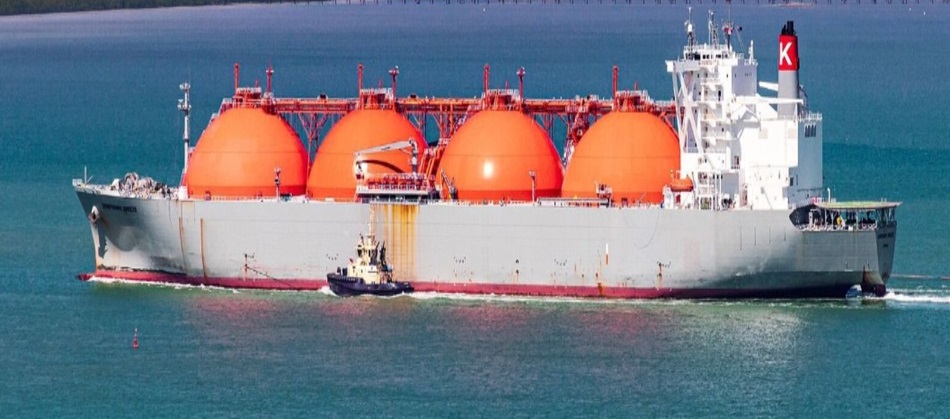
Moss Type LNG Tanker (Spherical Tanks) The tank structure is spherical in shape and it is located in the ship’s hull, with only half or most of the sphere being below the main deck level.
The outer surface of the tank shell is provided with external insulation, and the part of the tank above the main deck level is protected by a protective layer. A vertical tubular support is located from the top of the tank to the bottom, in which pipelines and access hatches for maintenance are located. This arrangement allows, in the event of any leakage in the tank, to prevent an LNG spill by accumulating it on a tray under the tank.
The drip chamber and central zone of the tank are equipped with temperature sensors to detect the presence of LNG. This acts as an additional leak detection layer for the tank. LNG is usually transported in this type of tank. The flexible foundation allows for free expansion and contraction based on thermal conditions, and such dimensional changes do not interfere with the primary structure of the hull.