Crankshaft speed sensors, also called speed sensors, are used to measure crankshaft speed; determine the position of the crankshaft (or even the position of the engine cylinder).
The rotational speed is calculated by the time period of the sensor signals, following the passage of the gear teeth.
The signal of the rotational speed sensor is one of the most important values for an electronic control system for diesel engine operation.
Having said that, let’s talk about the engine speed sensor device construction and it working principle.
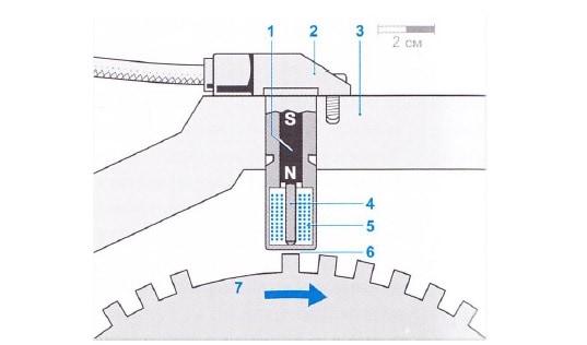
The sensor is mounted directly opposite the ferromagnetic pulsed wheel (flywheel) 7 fixed on the knee-shaft (see image below) and is separated from it by an air gap ( about 2mm gap).
The sensor contains a soft iron core 4 (pole tip), which is surrounded by an inductor 5. The pole tip is connected to a permanent magnet 1. The magnetic field passes through the pole tip inside the pulse wheel.
The intensity of the magnetic flux passing through the coil depends on what is opposite the sensor: the tooth or the gap between the teeth of the impulse wheel. Now the tooth causes amplification, and the gap, on the contrary, weakens the intensity of the magnetic flux.
Related post: Cause of an engine crankcase and piston Explosion
These changes induced in the coil an electromotive force(EMF) expressed in a sinusoidal output voltage which is proportional to the rotational speed of the crankshaft.
The amplitude of the variable is 83 voltage increases strongly with increasing speed (from a few mV to 100 V). Amplitude sufficient for sensor registration arises, starting with a frequency equal to 30 min-1.

How is the engine pickup sensor use to determine the position of the crankshaft
The number of teeth of the pulse wheel depends on the purpose of the application. Let’s take for example; in diesel engine control systems with solenoid valves, pulse wheels with 60 divisions are use, the number of teeth is 58. A large gap in place of missing teeth is a reference mark that corresponds to a certain position of the crankshaft and serves to synchronize the control unit.
Another type of impulse wheel has one tooth per cylinder. For example, a four-cylinder engine has four teeth, i.e., four impulses are issue in one turn.
The geometric shapes of the tooth and the pole tip must match each other. The signal processing system converts the output voltage with sinusoidal pulses with variable amplitude into a voltage with rectangular pulses with constant amplitude. These signals is process in the microprocessor control unit.
Setting and inspections of the engine speed sensor
It’s very important that the engineer who is employ for the up keeping of the engine needs to check and inspect this sensor periodically to avoid malfunctioning. This sensor may be set using the makers’ instruction manual. Some manufacturers use to place the gap between 1.5 to 2.5 mm, its recommended to keep the gap between the teeth about 2mm.
What happens in case of malfunction?
In case this sensor malfunctions during operation of the engine, it may send a wrong signal to the controller, which may trip the governor and there you have a blackout.
Also, it may happen after the engine stopped, while starting the engine again, the sensor might not communicate to the controller, which means the controller cant understand if the pickup time is due or not, which will cause your engine not to start. You may like to see other articles about the cause of engine not starting
How to understand the speed sensor is working condition or not?
Firstly, remove the sensor, check the surface for wears, if the surface after measurement meets with the recommendation of the maker, then check the relay attached to it (located in the engine local box). If you have electrical knowledge, you can use the electrical measuring meter to figure out if any problems with the device.
What can damage the sensor?
During engine running time, some particles may find their way in between the flywheel teeth( if not properly covered or protected). These metals might damage the magnet which is right on the tip surface of the sensor. Once this happens, it will be difficult for the sensor to work.
In the other hands; if you set the sensor too close, and properly have some gear teeth that are not equal, it may also damage the sensor surface during engine running time.
You might like to learn more about the difference between marine engine Turbocharger vs Supercharger
Conclusion
The sensor can serve your engine for a long time if;
- Maintain proper gap
- Flywheel area is protect from metal particles
- Check start teeth regularly, in case of damage change it, before it damages the flywheel teeth.
- On regular intervals, remove it and clean the surface to remove the oily grease ( for proper signal).
We hope with all of the above listed, you will have your engine speed sensor maintain.
Like the post? Share with friends and subscribe for more.